Abbreviations
AAL ATM Adaptation LayerABR Available Bit Rate
AFI Authority and Format Identifier
APDU Application Protocol Data Unit
ATM Asynchronous Transfer Mode
AvCR Available Cell Rate
AW Administrative Weight
BICI Broadband Inter-Carrier Interface
BGP Border Gateway Protocol
CAC Connection Admission Control
CBR Constant Bit Rate
CDV Cell Delay Variation
CDVT Cell Delay Variation Tolerance
CLP Cell Loss Priority
CLR Cell Loss Ratio
CLR0 Cell Loss Ratio objective for CLP=0 traffic
CNR Complex Node Presentation
CRM Cell Rate Margin
CTD Cell Transfer Delay
DBSP DataBase Summary Packet
DSP Domain Specific Part
DTL Designated Transit List
ES End System
ESI End System Identifier
FPGA Field Programmable Gate Array
FSM Finite State Machine
GUI Graphical User Interface
IDI Initial Domain Identifier
IDP Initial Domain Part
IDRP Inter Domain Routing Protocol
ILMI Interim Local Management Interface
IE Information Element
IETF Internet Engineering Task Force
ID Identifier
IG Information Group
IP Internet Protocol
LAN Local Area Network
LLC Logical Link Control
LGN Logical Group Node
MAC Media Access Control
maxCR Maximum Cell Rate
maxCTD Maximum Cell Transfer Delay
MBS Maximum Burst Size
MCLR Maximum Cell Loss Ratio
MCR Minimum Cell Rate
MIB Management Information Base
NNI Network-to-Network Interface
NSAP Network Service Access Point
OSPF Open Shortest Path First
PCR Peak Cell Rate
PG Peer Group
PGL Peer Group Leader
PGLE Peer Group Leader Election
PHP PNNI Hello Packet
PPDU Presentation Protocol Data Unit
PTSE PNNI Topology State Element
PTSP PNNI Topology State Packet
PNNI Private Network-to-Network Interface
PVC Permanent Virtual Connection
PVCC Permanent Virtual Channel Connection
PVPC Permanent Virtual Path Connection
QoS Quality of Service
RAIG Resource Availability Information Group
RCC Routing Control Channel
RD Routing Domain
SAAL Signaling ATM Adaptation Layer
SCR Sustainable Cell Rate
SDH Synchronous Digital Hierarchy
SDU Service Data Unit
SMDS Switched Multimegabit Data Services
SNPA Subnetwork Point of Attachment
SPDU Session Protocol Data Unit
SS Switching System
STM Synchronous transfer mode
STM-i Synchronous transport module i
SVC Switched Virtual Connection
TLV Type, Length, Value
TOTI Tietoliikenne- ja ohjelmistotekniikan instituutti
TPDU Transport Protocol Data Unit
UBR Unspecified Bit Rate
ULIA Uplink Information Attribute
UNI User to Network Interface
VBR Variable Bit Rate
VCC Virtual Channel Connection
VCI Virtual Channel Identifier
VF Variance Factor
VP Virtual Path
VPC Virtual Path Connection
VPI Virtual Path Identifier
List of Figures
Figure 2-1.	The Switching of ATM Cells			9

Figure 2-2.	Transmission path [3, p. 24].			9

Figure 2-3.	PNNI Hierarchy					11

Figure 2-4.	The Forming of The PNNI Hierarchy		13

Figure 2-5.	The FSM of The Hello Protocol			13

Figure 2-6.	Neigboring Peer FSM				14

Figure 2-7.	Peer Group Leader Election FSM			15

Figure 3-1.	The Forming of The PNNI Heirarchy I		20

Figure 3-2.	The Forming of the PNNI Hierarchy II		20

Figure 3-3.	The Forming of The PNNI Hierarchy III		21

Figure 3-4.	The Forming of The PNNI Hierarchy IV		22

Figure 4-1.	The Traffic parameters of The Setup Request	23

Figure 4-2.	Connection Setup Request I			24

Figure 4-3.	DTL Stack I					24

Figure 4-4.	Connection Setup Request II			25

Figure 4-5.	DTL Stack II					25

Figure 4-6.	Connection Setup Request III			26

Figure 4-7.	DTL Stack III					26

Figure 4-8.	Conncetion Setup Request IV			27

Figure 4-9.	DTL Stack IV					27

Figure 5-1.	The Scalability of The PNNI Protocol		28
List of Tables
Table 2-1	Hello packet [1, p.28]				12

Table 2-2	The Parameters of The Setup Request [4, p.12]	16

Table 2-3	The Contents of a PTSE				17

Table 2-4	Generic CAC Parameters				18

Table 2-5	VoD Parameter Mapping				19
1. Introduction
In the near future Asynchronous Transfer Mode (ATM) networks will
be the backbone of high bandwidth networks. The need for high
speed network arises from applications such as Video on Demand
(VoD), videophone etc.
ATM is the right platform for these applications. It provides high-bandwidth
connection orientated communication. Integrated broadband networks
are an extension of 64-kbit/s based integrated services digital
networks (ISDNs). Broadband integrated services digital networks
(B-ISDNs) will add a new feature to ISDNs: considerably higher
bit rates.
Because of the need for high bandwidth networks and the suitability of ATM to a large number of application types, the former CCITT (Comité Consultatif
International Télégraphique et Téléphonique)
selected ATM technology to be the implementation for the B-ISDN
networks [9, p.20].
The large interest by many network operators and vendors in ATM technology, led to the forming of ATM Forum in 1991. ATM Forum was formed with four original members. Currently
the ATM Forum membership includes more than 750 companies representing
all sectors of the communications and computer industries, as
well as a number of government agencies, research organizations
and users. ATM Forum gives recommendations on how to implement
the ATM technology. These recommendations have the tendency of
becoming de-facto standards which ITU (International Telecommunication
Union) and ANSI (American National Standards Institute) have to
adopt.
The ATM Forum realized that there was a need to provide an multi-vendor
interoperable method for switches and switching systems to interconnect.
The ATM Forum Technical Committee PNNI Subcommittee has been working
on defining a routing and signaling protocol for use between switching
systems. A draft specification was completed in June 1995 [5,
p.1].
The overall architecture of the Private Network-to-Network Interface
(PNNI) routing protocol is based on research and development work
done in the Internet Engineering Task Force (IETF) under the name
Nimrod.
Before 1996 switches from different vendors were not able to communicate
with each other. They didn't have a common language to communicate
with. The UNI 4.0 protocol that includes PNNI 1.0 was the solution
to this problem 2.
The purpose of the paper is to reveal the ATM routing according
to the Private Network-to-Network Interface.
2. Private Network-to-Network Interface
2.1 The Switching of ATM Cells
Fast routing of ATM cells is an important property of a well designed ATM switch.
Instead of switching packets - ATM nodes switch ATM cells. Network
nodes transmit calls through the network. The second OSI layer
becomes point-ti-point layer. This has been illustrated in Figure
1-1 [6, p.61-62].
UNI = User-to-Network Interface
NNI = Network-to-Network Interface
Figure 2-1. The Switching of ATM Cells
The ATM switch converts the input VPI (Virtual Path Identifier)
and VCI (Virtual Channel Identifier) pairs (per input port) to the output VPI/VCI
pairs ()per output port). The conversion is made by using an appropriate look-up table.
ATM switches make their routing decisions according to the contents
of the look-up table. See Figure 1-2.
Figure 2-2. Transmission path [3, p.24].
2.2 General About The PNNI Protocol
But how does one get to influence the contents of the look-up
table ? Earlier every vendor had its own protocol for this purpose.
Some switches' tables had to be configured manually.
The new signaling protocol Private Network-to-Network Interface
(PNNI) can establich, maintain, and delete connections dymanically.
In addition to traffic parameters, a user can specify Quality of
Service parameters in the setup request. With the QoS parameters the user can specify the quality of the connection.
People ofter assume from its name, that the Private Network-to-Network Interface is a LAN protocol, but in fact it is a protocol for world-wide networks. PNNI makes it possible to establish a connection with a set of traffic and QoS parameters to the other side of the globe. PNNI is a protocol for world wide connection of private ATM networks (a la the internet) and not for interconnection of public telecom operator ATM networks. Broadband Inter-Carrier Interface (BICI) is intended for the latter.
PNNI protocol consists of two sub-protocols:
- One protocol is defined for distributing topology information
between switches and clusters of switches i.e. peer groups. This
information is used in path calculations through the network.
PNNI topology and routing is based on the well-known link-state
routing technique. The PNNI Routing protocol is a member of the
class of routing protocols known as map based routing protocols.
These protocols operate by distributing descriptive information
about networks or portions of the network [5, p.3].
- Another protocol is used for signaling. It has mechanisms to
support source routing, crankbacks, and alternative routing of
call setup requests [1, p.11].
2.3 PNNI Hierarchy
The PNNI routing protocol views the world as a collection of peer
groups. Switches that have identical Peer Group ID (Group ID)
belong to the same peer group. Group IDs are specified at configuration
time. All members of the group maintain an identical view of the
group. There must be a path entirely within the set of switches,
between any two switches in the set.
Each node has its own topology database. Nodes view the word according
to the information presented in these databases.
A peer group leader (PGL) presents the peer group in the next
level of hierarchy. In the next level of hierarchy several PGLs
form a new peer group. The PGL is called a logical group node
in the next level of hierarchy. The PGL has a specific role in
aggregating and distributing of information for maintaining the
PNNI hierarchy.
The nodes in a peer group elect the PGL themselves. The criteria
for election is the leadership priority. The node with highest
leadership priority in a peer group becomes the PGL. A parent
peer group is defined by a peer group ID that must be shorter
than its child peer group IDs. Maximum peer group ID lenght is
13 octets i.e. 13 bytes.
Figure 1-1 shows how the PNNI hierarchy is established. Lines
between nodes represent real links between these nodes. Lines
between peer groups represent links between border nodes of these
peer groups.
Figure 2-3. PNNI Hierarchy
2.4 Distributing Topology Information and The Forming of The PNNI Hierarchy
Each PNNI node has its own topology database, which consists of
PNNI Topology State Elements (PTSE). This information is distributed
by the Hello protocol and flooding [1, p.156].
2.4.1 The Hello protocol
The Hello protocol has an instance on every link. As soon as the
node is turn on the Hello protocol starts sending Hello packets
to the neighbors. With the Hello packet the node describes itself
to its neighbors. Table 1-1 shows the fields in the Hello packet
[1, p.28].
| Size in bytes | Name of the field |
| 8 | PNNI Header |
| 2 | Flags |
| 22 | Node ID |
| 20 | Private ATM Address |
| 14 | Peer Group ID |
| 22 | Remote node ID |
| 4 | Port ID |
| 4 | Remote Port ID |
| 2 | Hello Interval |
| 2 | Reserved |
Table 2-1 Hello packet [1, p.28]
Neighboring nodes exchange peer group IDs in "Hello packets".
If they have the same peer group ID then they belong to the same
peer group, otherwise they belong to different peer groups. Neighboring
nodes with different peer group IDs are border nodes of their
peer groups. At the lowest level of hierarchy the peer group ID
is defined as a prefix of at most 13 octets on a private ATM address
[1, p.28].
Figure 2-4. The Forming of The PNNI Hierarchy
The states in the Hello FSM are illustrated in Figure 1-5. The
initial Down state will change to Attempt when the
phisical link is established. Way Inside states will be
entered if the two nodes are in the same peer group. Way Outside
and Common Outside states indicate that the nodes are
in different peer groups.
Figure 2-5. The FSM of The Hello Protocol
2.4.2 Neighboring Peer FSM
If the neighboring peers have turned out to be in the same peer
group the Hello FSM has entered the state 2-Way Inside.
This triggers the AddPort event in the Neigboring Peer
FSM. Now the Neigboring Peer FSM has an active instance on the
link in question. With the help of this FSM nodes belonging to
the same peer group exchange PTSEs with each other. At the end
of this process every node in the peer group will have an idenfical
toplogy database. Figure 1-6 illustrates the PTSE exchange process.
Figure 2-6. Neigboring Peer FSM
2.4.3 Peer Group Leader Election FSM
Peer Group Leader Election (PGLE) FSM dynamically chooses a leader
for the peer group. PGL (Peer Group Leader) represents the peer
group in the next level of hierarchy. PGL Election starts when
the Hello protocol has started on all links. There is only one
instance of PGLE FSM running in one node[7, p.231].
Figure 2-7. Peer Group Leader Election FSM
2.4.4 Flooding
Flooding is the mechanism used to advertise links [1, p.29]. Flooding
is the reliable hop-by-hop propagation of PTSEs throughout a peer
group. It insures that each node in a peer group maintains an
identical topology database.
2.5 PNNI Signaling
Signaling protocols are used for call and connection setup in
communication networks. These protocols exchange information that
enables calls to be established and controlled.
ATM signaling is a set of protocols used for call/connection setup
over ATM interfaces. PNNI signaling introduces new features that
enables dynamic call setup [1, p.54].
In order to ensure that routing follows a loop free path, and
to allow source to utilize local policy, the path for a signaling
is specified in the message in the form of a hierarchically complete
source route known as a Designated Transit List, or DTL, stack
5, p.5.
The complex routing problem is divided into smaller problems i.e.,
routing across the peer group. The implementation of these problems
is not covered in the PNNI protocol which makes is all the more
interesting.
In the setup request one has to determine the values for the parameters
listed in table 1-2. Not all parameters are available for a specific
Service Category.
Table 2-2. The Parameters of The Setup Request 4, p.12
Link metrics are either concave or additive. If the path p has
two links ab ja bc, the parameter value for the whole path is
calculated:
- d(p) = min[d(ab), d(bc)], if the link parameters are concave, for example PCR
- d(p) = d(ab) + d(bc), if the link parameters or additive, for example maxCTD
The nodes make routing decisions according to the knowledge they
have in their topology database. Table 2-3 show the contents of
a PTSE.
| Name of the field | Size in bytes |
| PTSP Header | 42 |
| PTSE Header | 20 |
| Nodal State Parameter IG | 204 |
| Node Identification IG | 108 |
| Internal Reachable ATM Address (IRA) Prefix | A |
| IRA IG Overhead | 8 |
| Exterior Reachable ATM Address (ERA) Prefix | B |
| ERA IG Overhead | 402 |
| Horizontal Links IG | 228 |
| Uplink IG | 262 |
Table 2-3. The Contents of a PTSE
Horizontal Links IG field includes the connection the node in
question has inside its own peer group. The contents of Horizontal
Links IG is represented below in more detail. The Uplink IG contains
respectively connections to other peer groups.
type
	Horizontal_Links_IG = record
		VP_Capability: boolean;
		Remote_Node_ID: string;
		Remote_Node_Order: integer;
		Remote_Port_ID: integer;
		Local_Port_ID: integer;
		CBR: Outgoing_Resource_Availability_IG;
		rt_VBR: Outgoing_Resource_Availability_IG;
		nrt_VBR: Outgoing_Resource_Availability_IG;
		ABR: Outgoing_Resource_Availability_IG;
		UBR: Outgoing_Resource_Availability_IG;
	end;

type
	Outgoing_Resource_Availability_IG = record
		Flag: Traffic_Class;
		Reserved: boolean;
		Cell_Loss_Ratio: integer;
		Maximum_Cell_Rate: integer;
		Available_Cell_Rate: integer;
		Cell_Transfer_Delay: integer;
		Cell_Delay_Variation: integer;
		Administrative_Weight: integer;
		Cell_Rate_Margin: integer;
		Variance_Factor: integer;
	end;
2.6 Generic Call Admission Control
In PNNI routing the link parameters are represented as generic
CAC parameters. These parameters are:
- Available Cell Rate
- Cell Rate Margin
- Variance Factor
When the user has entered all the setup parameters in the setup request, the generic CAC compares the requested parameters and the available link parameters.
If the requested bandwidth is not available or some QoS parameter
value can not be met on some link, the connection can not be established.
In a situation like this a crankback mesage will be sent to the
upstream direction.
There is a correlation between the setup request parameters and
the allocated bandwith [1 ,p.148]:
CBR:
Setup^.Forward_Bandwidth := Setup^.Forward_PCR;
nrt_VBR ja rt_VBR:
	X := Setup^.Forward_PCR / Setup^.Forward_SCR;
	if X > 39 then
		C := Setup^.Forward_SCR * ((0.0145*X) + 4.22)
	else
		if X > 5 then
			C := Setup^.Forward_SCR * ((0.042*X) + 3.14)
		else
			C := Setup^.Forward_SCR * ((0.48*X) + 0.52);

	Setup^.Forward_Bandwidth := round(C);
Parameters that influence the allocated bandwidth in the variable
bit rate connection are PCR (Peak Cell Rate) and SCR (Sustainable
Cell Rate). Table 2-4 show a few relations between these parameters.
| PCR | SCR | BW |
| 40 | 20 | 30 |
| 100 | 10 | 36 |
| 1000 | 10 | 57 |
Table 2-4. Generic CAC Parameters and Allocated Bandwidth in VBR Service Category
2.7 VoD User Interface and Parameter Mapping
The user interface of a VoD server could have a set of quality classes:
- High quality
- Medium quality
- Low quality
The limitation to three options is done to make the user interface
simple. A typical user does not have the ability to fill in all
the traffic parameters and Quality of Service parameters. There
are a few parameter configurations that correspond to the three
VoD quality options.
One possible parameter mapping between these three quality classes
and PNNI parameters is shown in Table 2-5. The video in question is not
compresses, which makes the broadcast CBR-service.
| High quality | Medium quality | Low quality | |
| Traffic parameters: | |||
| PCR | 4717 | 1474 | 151 |
| SCR | no | no | no |
| MBS | no | no | no |
| MCR | no | no | no |
| CDVT (1-99) | 5 | 50 | 70 |
| QoS parameters: | |||
| peak-to-peak CDV (s) | 100 | 1000 | 10000 |
| maxCTD (s) | 1000000 | 1000000 | 1000000 |
| CLR (10-n) | 12 | 9 | 9 |
Table 2-5. VoD Parameter Mapping
3. The Forming of The PNNI Heirarchy
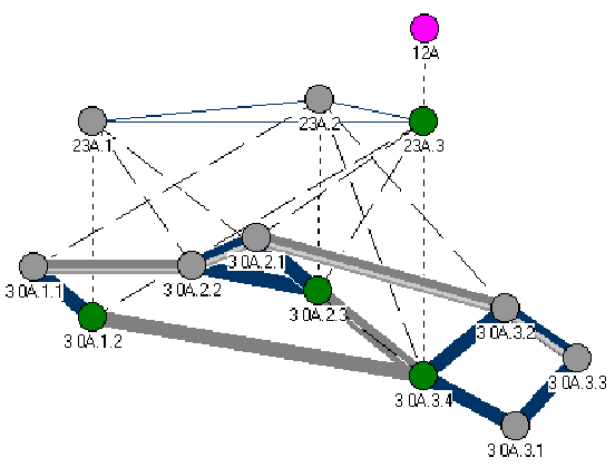
The following picture sequence is a series of screenshots from
the PNNI emulator, that I have developed.
3.1 Situation I
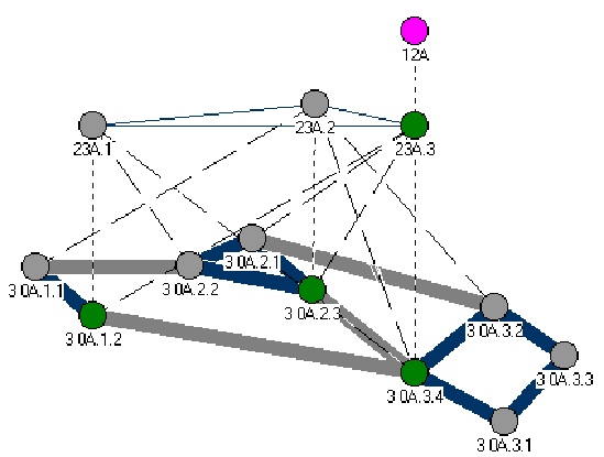
All the nodes are turned on simultaneously. All the nodes have only PTSEs of themselves. Hello packets are sent to the neighbors, but no one has received a Hello packet yet.
Figure 3-1. The Forming of The PNNI Heirarchy I
3.2 Situation II
The nodes have received Hello packets from their neighbors. Each node now knows if the neighbor belongs to the same peer group or not. The links that connect two nodes in the same peer group are darker in Figure 3-2.
Figure 3-2, The Forming of the PNNI Hierarchy II
3.3 Situation III
The nodes have exchanges the PTSEs with their neighbors with the
assistant of Neighboring Peer FSM. Each peer group has elected
their leader that will represent the peer group in the next level
of hierarchy. Nodes A.1.2, A.2.3, and A.3.4 have become leaders
of their respective peer groups A.1, A.2, and A.3.
Figure 3-3. The Forming of The PNNI Hierarchy III
3.4 Situation IV
In the next level of hierarchy the LGNs have exchanges Hello packets,
PTSEs, and elected the PGL.
Figure 3-4. The Forming of The PNNI Hierarchy
4. Connection Establishment
When the PNNI hierarchy is formed, the nodes are ready to serve
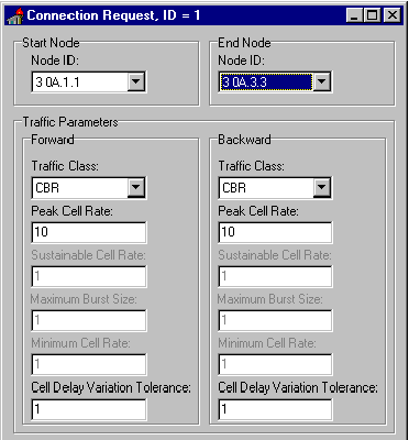
the attached clients. The Client attached to the node A.1.1 requires
a connection to the node A.3.3 or to the end system attached to
the node A.3.3 .
Figure 4-1. The Traffic parameters of The Setup Request Received By The Node A.1.1
4.1 Situation I
Node A.1.1 has found the path to node A.3.3. The path goes through
the group A.1, A.2, and A.3 . A.1.1 must find to path to the peer
group A.2. A.1.1 happens to have a direct link to the node A.2.2,
which belongs to the group A.2. So A.1.1 forwards the setup request
to the node A.2.2 .
Figure 4-2. Connection Setup RequestI
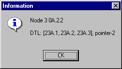
DTL stack received by the node A.2.2:
Figure 4-3. DTL Stack I
4.2 Situation II
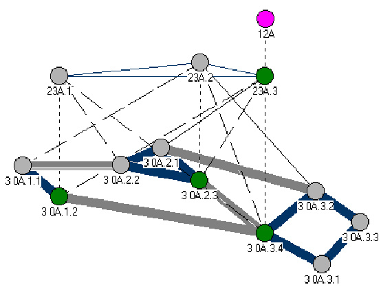
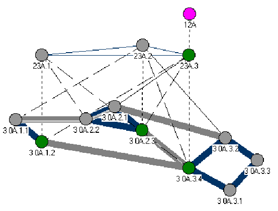
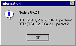
Node A.2.2 notices that it must find the path to the peer group A.3. It does not have a direct link to that group, so it must add a new DTL to the DTL stack. A.2.2 forwards the setup request to A.2.1 .
Figure 4-4. Connection Setup Request II
DTL stack received by the node A.2.1:
Figure 4-5. DTL Stack II
4.3 Situation III
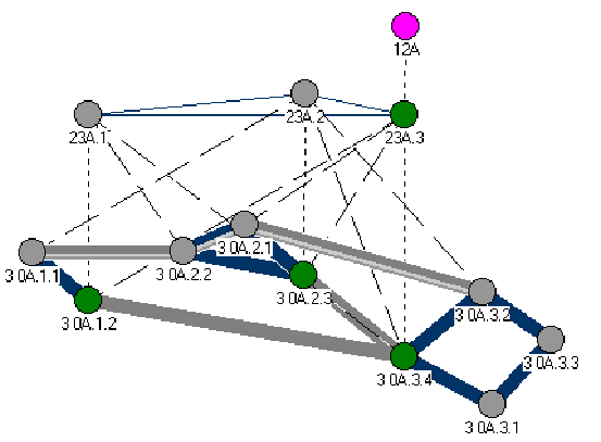
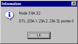
Node A.2.1 notices that it is the last node of the top DTL. It pops the DTL and deletes it. The new top DTL has A.3 as the next element. A.2.1 finds the path to group A.3. A.2.1 has a direct link to A.3.2, which belongs to the group A.3. A.2.1 forwards the setup request to the node A.3.2 .
Figure 4-6. Connection Setup Request III
DTL stack received by the node A.3.2:
Figure 4-7. DTL Stack III
4.4 Situation IV
Node A.3.2 receives the setup request and notices that the top DTL pointer is in the end of that DTL. A.3.2 pops the top DTL and deletes it. It must still find the path to the node A.3.3, which is defined as the end node in the connection setup request by the user. Node A.3.2 has a direct link to the node A.3.3, so it forwards the setup request to it.
Figure 4-8. Conncetion Setup Request IV
DTL stack received by the node A.3.3:
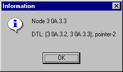
Figure 4-9. DTL Stack IV
5. Summary And Conclusions
A hierarchy mechanism ensures that this protocol scales well for
large world-wide ATM networks. The PNNI protocol can have up to
104 successive child/parent related peer groups. There are usually
20 nodes in a peer group. This means that there can be as many
as nodes in the PNNI domain. This simply
means that the PNNI domain does not have to be private as the
name PNNI (Private Network-to-Network Interface) applies. The
world-wide ATM networks can be more than adequately configured
with less than 10 levels of ancestry [2, p.27]. This is illustrated in Figure 5-1.
Figure 5-1. The Scalability of The PNNI Protocol
The PNNI protocol enables many applications to conquer the entertainment
or business markets. In the existing internet infrastructure it is impossible to guarantee any quality of service. The packets are transfered with best effort. There are no guarantees on the transfer time. In addition the IP packets can be deleted if the TTL (Time To Live) field becomes zero. For example, interactive multimedia is one such promising application, which additionally requires dynamic high bit rate bandwidth allocation. There is a whole new media out there waiting to be exploited.
References
- [1]
- ATM Forum, The ATM Forum 94-0471R15 PNNI Signaling Description, 1994, p. 363
- [2]
- ATM Forum, Private Network-Network Interface Specification Version 1.0, 1996, p. 366
- [3]
- Rainer Händel, Manfred N. Huber, Stefan Schröder, ATM Networks, ed. 2, Addison-Wesley, 1994, p. 287
- [4]
- Matti Tommiska, "Optimization of ATM routing with an FPGA-based hardware accelerator", Master's Thesis, TKK 1996, p. 12
- [5]
- Joel M. Halpern , The Architecture and Status of PNNI, Newbridge Networks Inc., 1995, pp. 1 - 8
- [6]
- Walter J. Goralski, Introduction to ATM Networking, McGraw-Hill, 1995, p. 384
- [7]
- Gurdip Singh, "Leader Election in the Presence of Link Failures", IEEE Transaction on Parallel and Distribution Systems, Vol. 7, 1996, No. 3, pp. 231-236
- [8]
- Harry J.R. Dutton, Peter Lenhard, Asynchronous Transfer Mode (ATM), ed. 2, Prentice Hall PTR, 1995, p. 264
- [9]
- Kari Seppänen, ATM-verkon virtuaalipolkukonfiguraation optimointi", Master's Thesis, TKK 1995, pp. 16 - 25


